Let’s assume for the moment that there is an extra glob (How’s that for a technical term!) of rubber on the edge of the tread of a tire – and that the tire is mounted on a rim and inflated. If this glob has significant weight, it could cause a vibration in the vehicle.
Let’s assume the glob weighs 1 ounce, and the tire is 30″ in diameter, the tread is 6″ wide, the rim is 15″ in diameter, and the rim width is also 6″ wide.
Just to get a bearing on things, a 1 oz. glob of rubber will have a volume of about a strip of rubber 3″ wide, 12″ long, and 0.050″ thick.
The dimensions of imbalance are “distance – force”, the same as torque. Usually this is expressed in units that are easy to work with and using the English system this would be: inch-ounces.
In our example, the tire and rim assembly would have an imbalance of 15 inch-oz. The centrifugal force being generated is:
F = mrω2
Where:
F = Force
m = mass
r = radius of rotation
ω = rate of rotation
The important points are:
- The force is proportional to the mass.
This means that rims (wheels), which are machined and generally have less dimensional variation, would generate less imbalance than the tire, which is molded and inflated. The tire has more opportunities to be dimensionally more variable.
- The force is proportion to the diameter.
This means that if the weight we add is at the rim diameter, then it has to be more than if we apply it at the tire tread. In our example, the 1 oz weight at the tread surface (30″ diameter) is counteracted by TWICE the weight (2 oz) at the rim diameter (15″).
This also means that, all other things being equal, the rim creates much less imbalance than the tire does.
- The force is proportional to the SQUARE of the speed.
This means that more care needs to be taken for racing tires.
BUT
Vehicle suspensions have resonant frequencies in particular speed ranges, so the speed isn’t as important as you may think.
Side note: I am going to use the phrase “assembly” to mean the rim with a tire mounted on it, inflated, and all the ancillary components needed to make that work, such as the valve.
I am also going to use “tire” to mean only the rubber part of the assembly.
But I am going to use “rim” to mean the thing the tire is mounted on. Some of you may object to that and want to call that a “wheel” – and I am not unsympathetic to that. However, I want this to be as clear as possible and I have found that most people will understand “rim” to mean what I want it to mean, and “wheel” less so. Sorry if this annoys you.
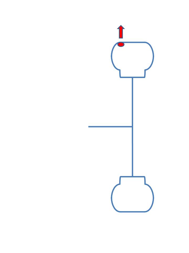
| Static Balance: This is also known as “bubble balance” since one of the devices used is a form of a level which uses a bubble of air floating under a curved piece of glass. The glass usually only has a “bulls eye”. (look at the photo above.) Since the weight needed is to be mounted on the rim flange, how much weight is needed? The assembly is 15 in-oz out of balance, so to compensate for that at a 15″ diameter (7½” radius), the weight has to be 2 oz. So where to put the weight? The bubble points to the location. That brings us to: |
Dynamic Balance:
So let’s take our case and see:
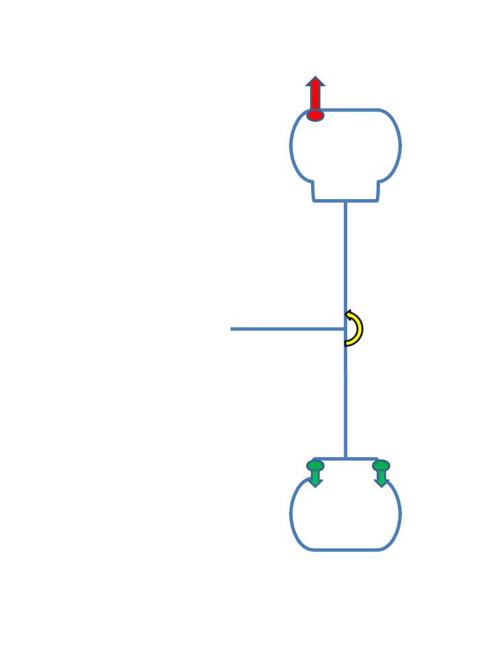
Put the weight on the outside at the flange? (in green)
When the 2 masses (the “glob” and the balance weight) revolve that introduces an oscillating moment (torque) at the axle – illustrated by the yellow arrow. This, of course, causes a back and forth twisting action, – and a side-to-side vibration.
Split the weights between the inside and outside?
That’s better, but there is still a moment at the axle, albeit half the value compared to above.
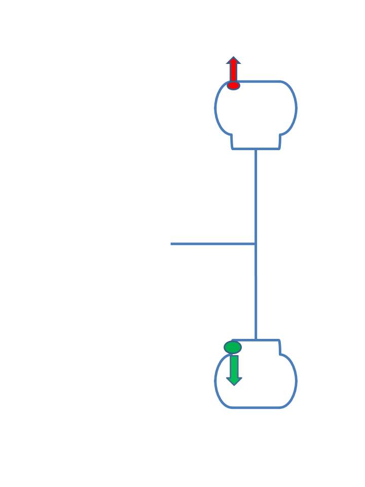
Put the weight on the inside?
In our case that works exactly the way it should. It completely balances everything and does not introduce a moment at the axle.
Notice that we’ve handled both the static balance as well as the dynamic couple. It should be obvious that dynamic balancing is always better than just static balance.
Runout:
You could call this “out of round”.
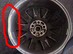
This is where one or more of the components is not round. It could be the rim, or it could be the tire, but the net result is the assembly is not round.
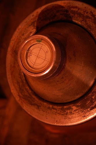
This can take many forms, including a flat spot, off center, etc. In the case of the photo to the right, the rim is obviously bent. Putting a tire on this rim is not going to make the situation better.
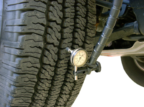
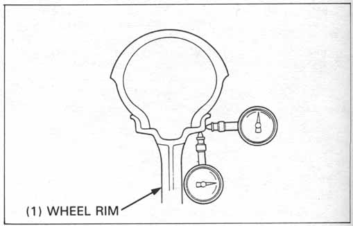
You can also measure the runout of the assembly – as indicated by the photo to the left.
The problem here is that this merely measures the unloaded assembly, and that doesn’t cover the whole story.
Uniformity:
This is sometimes called “force variation” or “road force”, but it means the same thing.
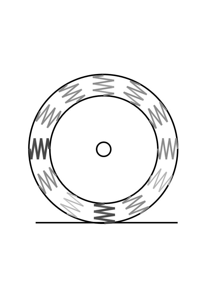
This is a little more complex. If you imagine a tire as a series of springs and as each spring comes into contact with the ground, it deflects according to its spring rate. Since each spring has a different spring rate, there will be different deflections around the tire.
The different shades indicate different strength springs around the tire.
We could measure this in a number of different ways.
- Measure the deflection
- Measure the force generated
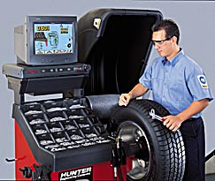
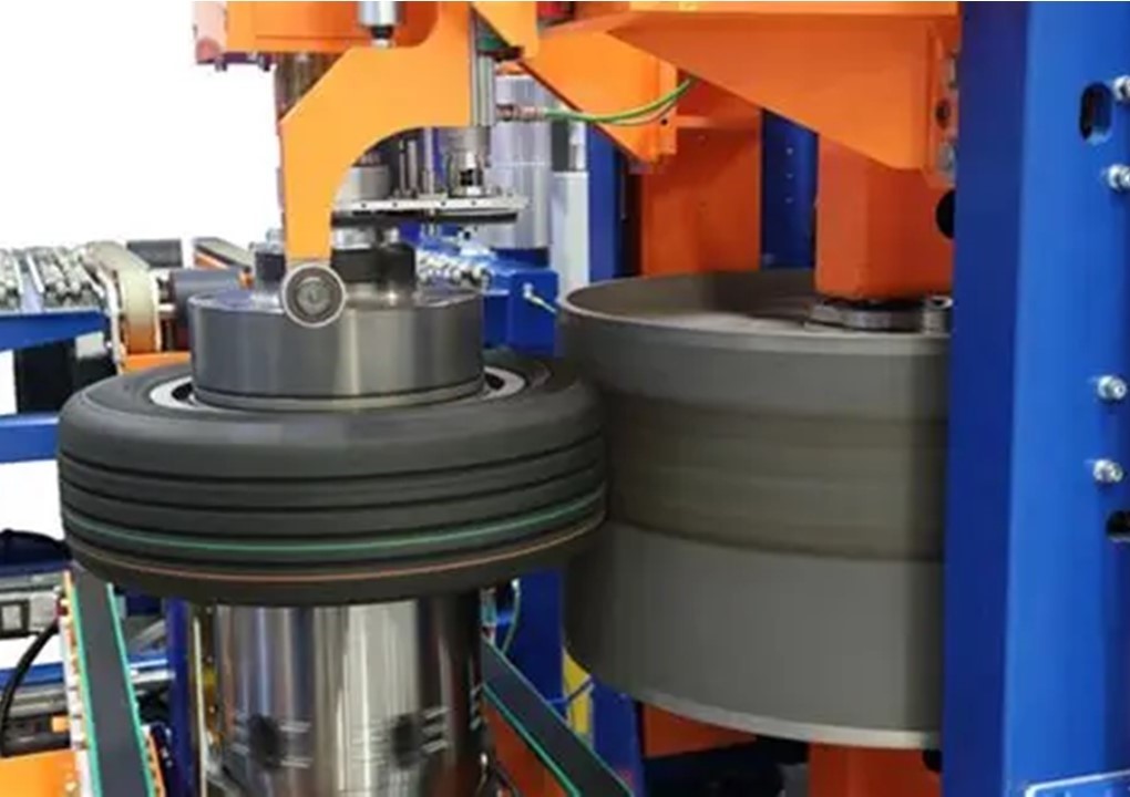
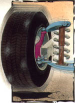
Because the vehicle “feels” the force, this is the most common way – and the way tire companies measure it – with a Tire Uniformity Grader (TUG) – Photo to the left. Notice how large the road wheel is.
These machines are big, heavy, and highly precise, but can process a lot of tires quickly. The last time I asked (about 2005) the price tag was over $600,000 each. Needless to say, they are beyond the price range of an ordinary tire shop.
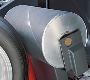
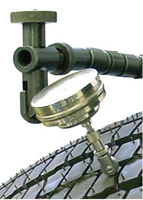
However, there are several machines which are within reach of a tire shop – most notably the Hunter GSP9700 RoadForce machines.
Probably the biggest disadvantage of these machines is the small load wheel. Because the road surface is flat, any wheel is going to emphasis a smaller area of the tire – and misread nonuniformities spread of a large area.
Nevertheless, they are good for their purpose – sorting out which assembly may be the problem assembly. These machine should not be used to sort through new tires, nor to decide if a new assembly is acceptable (even though that this happens a lot.)
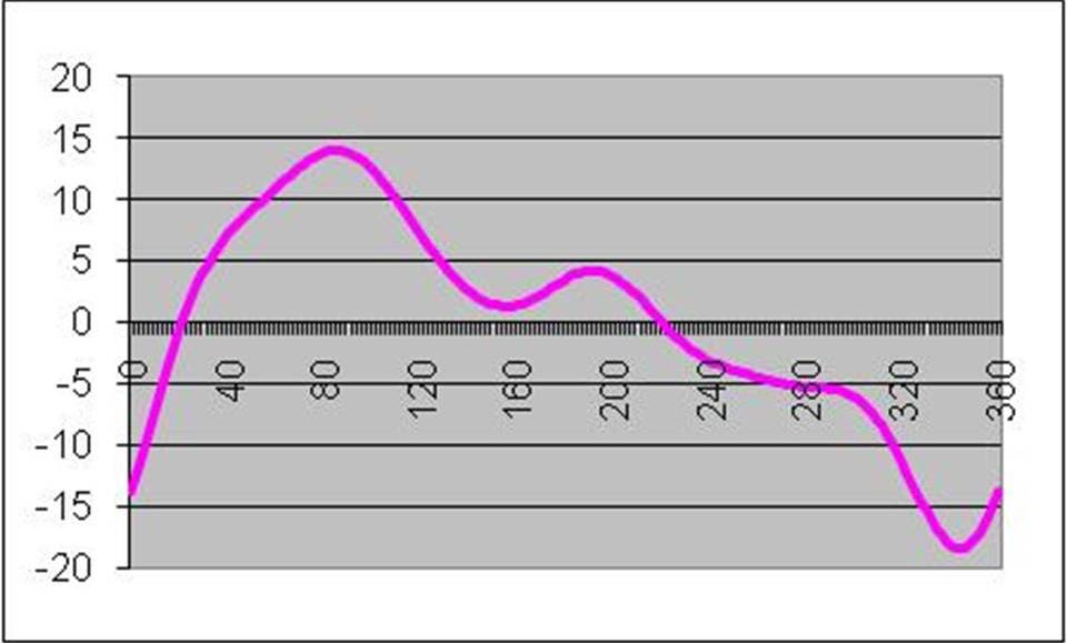
Here’s what you get when you measure a tire on a uniformity machine. This is a plot of degrees vs force variation. Peak to Peak, the values range from +14 to -18.
This is usually called the “Composite”, but Peak-to-Peak (P-P) is also used.
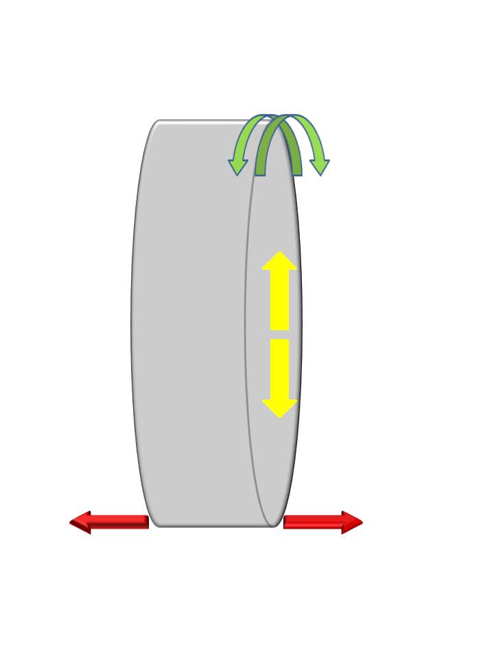
It’s time to talk about directions:
Normally, we think of “up-down”, “left-right”, “near-far”, commonly called Cartesian Coordinates. But tires have a peculiar symmetry and you can use this to your advantage.
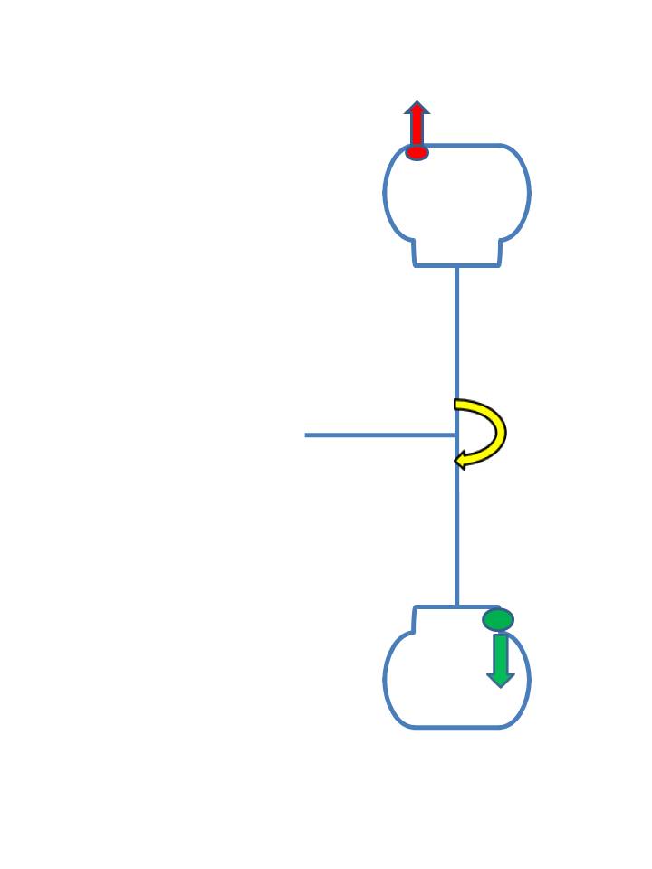
If you look at the front of the vehicle, side to side is commonly called the “lateral” direction – and that applies to tires as well – the Red arrows.
If you look at a tire from the side, it is a circle. You can reference any part of the circle and the tire is the same. So coming out from the center is known as the “radial” direction – the Yellow arrows.
The contact patch is directly under the hub, so from the perspective of the vehicle this becomes the up and down direction.
Lastly, the front to back direction from the vehicle’s perspective could be called “Fore – Aft”, but from the tire’s perspective this could also be the “Tangential” direction – the Green arrows.
One peculiar aspect of vehicle suspensions is known as the “wheel hop frequency”. It’s the resonant frequency of the suspension – which is in essence a “spring-mass-damper system”.
If done correctly, a vehicle will have spring rates and damping coefficients such that the wheel hop frequency occurs somewhere in the 50 to 70 mph (80 to 115 kph) range. At that particular range of speeds, a repeating force can set off an undamped oscillation – a vibration.
An imbalance can do that – OR – the first harmonic of radial force variation can do that.
First Harmonic:
means the once per revolution contribution of the composite waveform. Obviously, the 2nd Harmonic is the twice per revolution contribution. And so on. There are an infinite number of harmonics.
The good news is that for tires (rims, too!), the 1st harmonic is usually much larger than the 2nd, which is much larger than the 3rd, etc.
Here’s that same output from a uniformity machine – but I’ve added the first harmonic. It’s a “best fit” sine wave. There are several mathematical techniques that can be used to determine what the best fit is – and in particular, its magnitude. I’m not well acquainted with them, and you’re probably not interested anyway. So let’s just agree that we’ll accept that it can and is done.
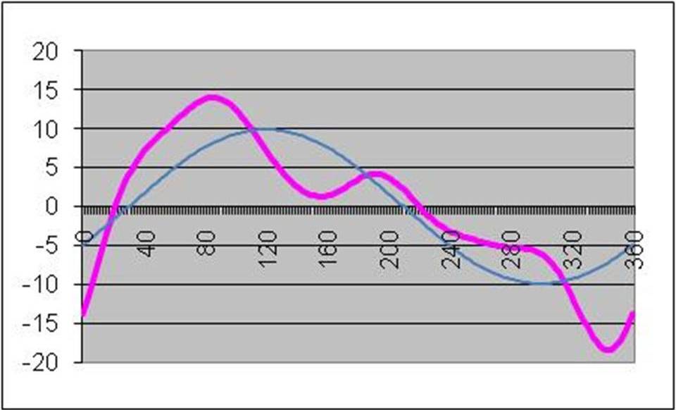
(Psst! I just want to tell you I cheated with the graph. I started with specifying several harmonics and then added them together to get the composite curve.)
| Wheel hop reacts to the up and down force – or put into tire coordinates, the radial direction. We abbreviate the 1st harmonic of the radial force variation as “R1H”. This value become really important in quantifying if an assembly is too high. Notice several things: |
- The magnitude of the composite curve (pink) is much larger (+14# to -18#: average = 16#) than the first harmonic curve (blue – ~10 pounds). We tire engineers would call this a 10# tire, since it is the first harmonic is the one that drives the vibration.
- The 1st Harmonic’s peak does not line up with the composite’s peak. In fact, it is in a different location. That is one of the reasons why doing runout on a tire does not always yield good results.
Side Note:
Rims also have non-uniformity – and harmonics – but you can directly measure non-uniformity as run out. About 0.001″ of runout ~= 1 pound of force variation. While the 1st harmonic’s peak could be in a different location than the composite’s peak, the way wheels are machined means the 1st harmonic’s peak is usually very close to the composite’s peak.
As I said earlier, vehicle suspensions react strongly to Radial 1st Harmonics. Not so much with Lateral 1st Harmonic, and even less to Tangential force variation.
Match Mounting:
Because both rims and tires can have 1st harmonics, you can take advantage of this by mounting the tire’s R1H high point with the rim’s R1H low point.
To make this easier, vehicle manufacturers will ask their rim and tire suppliers to mark those points. The photo to the left shows those marks. This is a Ford. (from the color and shape of the peel-off stickers)
| Other vehicle manufacturers require different marks. Revision November 2025: The paragraph above is dated. Hardly anybody uses the valve hole as any kind of mark nowadays. /end revision In the replacement market, there is no standard way of marking the rim, nor marking the tire. Some tire manufacturers use a different color, some don’t mark the tire at all. Plus it is questionable what the rim manufacturers are doing. Some folks have said that the red dots on the tires (if they have them) should be matched up with the valve. It is common for the red dot to indicate the R1H location, but since the valve hole is not indicative of anything, this is a pointless activity. The way to do this would be to measure the rim – and that’s where the Hunter Revision November, 2025: Hunter has changed the name of the balance machines that can due uniformity measurements to “RoadForce” machines. Here a link to find one: Find Hunter Equipment | Hunter Engineering Company® /end revision However, it is common nowadays for folks to “say” that the valve hole is the heavy spot of the wheel, because that’s where the TPMS sensor is. This might be true, but I have not seen anyone verify this. But what this would do is minimize the amount of weight needed to balance a tire. That doesn’t not make the balance better. A balanced assembly is a balanced assembly regardless of how much weight it takes. I hope it would be obvious from all this that force variation has nothing whatsoever to do with balance because the weight distribution within a tire is not tied to uniformity and therefore, neither is the balance. Put another way, you would be mistaken if you think matching the red mark is reducing the balance weights needed. |
MORE Additional information added after the article was first published:
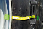
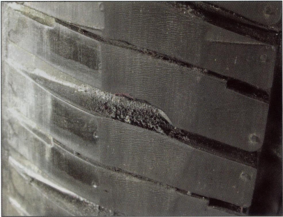
Grinding: I was reminded that grinding the face of the tread to reduce the force variation used to be a common practice, so I need to talk about it.
The photo to the right is what a POOR example looks like.
Grinding is usually used to reduce the R1H value of the tire. although it can be used to change quite a few different uniformity properties, including conicity. When done correctly, the grind should be barely visible. In other words, the grind should not be deep (we are talking thousandths of an inch, here!), there should be very little dust and there should be an ever so slightly visible texture, with, perhaps, a little bit of “heel and toe”. Sometimes a bit of the stripes or the letters would be removed.
To my knowledge, no adverse affects have been found when tires are ground properly.
Vehicle Sensitivity and Vibrations:
Every vehicle has a certain level of sensitivity to a wheel end vibration. This sensitivity will vary by wheel position – front to rear, and somewhat from side to side – making each wheel position different.
As a general rule, the most sensitive wheel position (to the driver, which is who is usually judging the vehicle) is the Left Front, and the least sensitive position is the one farthest away – the Right Rear.
Tires are a major contributor to wheel end vibrations, but sometimes they get unfairly judged as the sole source of the problem, because there are many vehicles that have incredibly stiff chassis’, which aggravates the situation.
To the right is my take on the relative importance for various components that can contribute to wheel end vibration. Please note the values are unimportant, except for their relative value to each other.
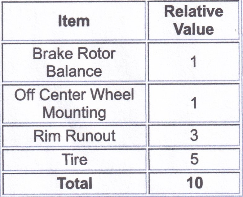
Please note: There are other components, but only rarely do they cause vibrations.
Also note this assumes the tire and wheel assembly is balanced off the vehicle.
If the vehicle has a sensitivity to values over 10, then this vehicle will not have a perceptible vibration. Since all these values are maximums, then it doesn’t matter if any component is at the maximum – no perceivable vibration.
But let’s examine all these components a little more closely:
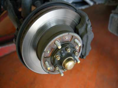
Brake Rotor Balance:
A brake rotor is made out of metal. It is machined, and its outer diameter is much smaller than any other wheel end component That’s why vehicle manufacturers put relatively tight limits on brake rotor imbalance and with such low values, these couldn’t possibly be the source of a vibration, Right?
But if you look closely at the rotors, you may find balance weights in the vents, or grind marks on the outer rim, so does that mean they are always in balance? I think not!
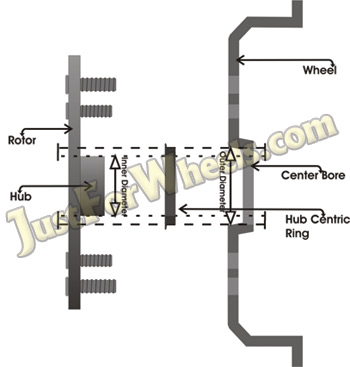
Off Center Wheel Mounting:
Many wheels are supposed to pilot on the center hub, however there is a little clearance so the wheel will slide easily onto the hub. Since the hub is machined and the wheel is probably machined, this also should never be the source of a vibration.
But many aftermarket wheels DO NOT pilot on the hub. They are piloted by the lugs (lug centric, as opposed to hub centric). It is widely known that the lugs are very difficult to make on-center and perpendicular to the mounting surface. For this reason, most aftermarket wheels come with hub rings, that have to be sized correctly for your particular vehicle.
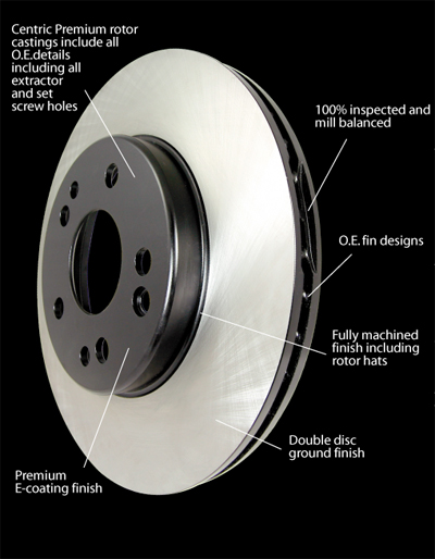
Rim Runout:
Alloy wheels are generally machined, so in theory, they should have no run out, but variations in mounting the wheel during the machining process results in some small amounts of run out. Even though these are also made of metal and machined, because they are larger than brake rotors (and therefore more difficult to manufacture) and at a larger diameter, vehicle manufacturers’ tolerances are typically larger than brake rotors for both imbalance and runout.
Tires:
These are just large balloons, making them difficult to manufacture to tight tolerances. Plus they are the largest diameter items and therefore small variations will have large effects. For this reason vehicle manufacturers also allow tires to have the largest tolerances.
So what happens when there is a sensitive vehicle (say, with a limit value of 6#) and we use the same tolerances. OPPS!! Vibration!
Since they want to satisfy the customer, they’ll want to change something – something easy!
So they change the tire – and let’s say the next tire has an average value of 2#. Now the total is 7 #, but the problem is better, ergo, the problem must be tires.(?)
It’s only when the tires are near zero that the problem completely goes away. But the fact is that changing tires can make the problem go away leads many people to think the problem is strictly related to tires.
A complicating factor is that tires must be mounted on a rim and therefore, the variation of the rim affects the tire variation, sometimes even magnifying the variation.
| Let’s take another example: If the brake rotor has a lateral variation at the hub of 0.002″ – a very small value – but it is occurring at 2″ in diameter, then the variation at the tread surface (30″ in diameter) would be 15 times that value – 0.030″. Any variation of the other components could add to that, making the vehicle vibrate, even if the tire is PERFECT!! Care must be taken when dealing with a vibrating vehicle to assure that the whole picture is understood. When a change in tires does not fix a problem, the next logical step is to look at the rims. Don’t forget that the Hunter GSP9700 has a built in tolerance for wheels, but its value is the same as the entire assembly – meaning that a wheel with an excessive amount of run out will be judged as acceptable. |